Geometry
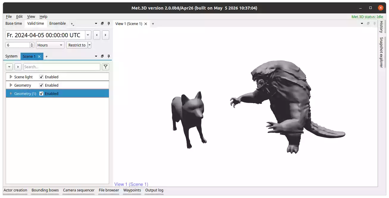
Fig. 19 Two geometry actors with a loaded OBJ file each.
Overview
The geometry actor renders a Wavefront OBJ (.obj) mesh into the 3-D scene.
This is useful for overlaying additional 3-D geometry such as terrain models, cityscapes,
flight tracks, or custom model-derived surfaces in a meteorological context.
Key features:
.objfiles can be loaded via a graphical file dialog.The vertical coordinate of the mesh (Z component) can be interpreted as pressure (hPa), height (m or km), or passed through as graphics-space Z.
Basic transformations (translation, rotation, scaling) can be applied to align the mesh with other data.
The mesh can be coloured using a variable from a gridded dataset or using per-vertex attribute data from an accompanying attribute file.
The mesh can be rendered as a solid surface or in wireframe mode.
Loading an OBJ File
Open the Geometry → Configuration panel.
In the OBJ file tab, click on
...to open a file browser.Select a Wavefront OBJ file from your local file system.
Important
Select the correct Vertical coordinate units (hPa, m, km, or
graphics space Z) to ensure correct vertical alignment with other data in the scene.
Mesh Transformation
The actor provides basic transformation tools for manual alignment under Geometry → Configuration → Mesh transformation:
Position: Shift the mesh in X, Y, or Z direction. We recommend using the gizmo in actor interaction mode to interactively place your mesh in the scene.
Rotation: Rotate around the principal axes. You can also use the interaction gizmo to explore different rotations.
Scaling: Uniform or non-uniform scaling.
Colouring by a Gridded Variable
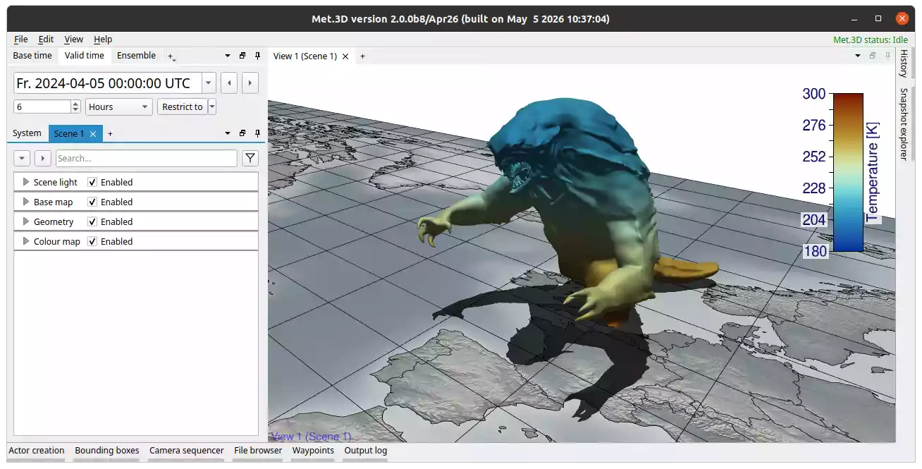
Field data from a gridded dataset can be mapped onto the mesh surface via Met.3D’s variable and transfer function system.
Add a colour map to the scene.
Navigate to Geometry → Variables and click Add new variable to link a gridded variable.
Under Geometry → Variables → your variable → Rendering → Transfer function, assign the transfer function.
Colouring by Per-Vertex Attributes
Alternatively, the mesh can be coloured using per-vertex scalar data loaded from a plain
text attribute file (.txt).
Load the attribute file via Geometry → Configuration → Attribute file.
Once an attribute file is loaded, the Transfer function selector in the Configuration panel becomes active. Assign a transfer function to map the attribute values to colours.
The attribute file is a plain text file with the header @1 on the first line,
followed by one floating-point value per line in the order of the vertices in the OBJ
file:
@1
6.908451020717621e-02
6.831714510917664e-02
7.153325527906418e-02
6.184569373726845e-02
...